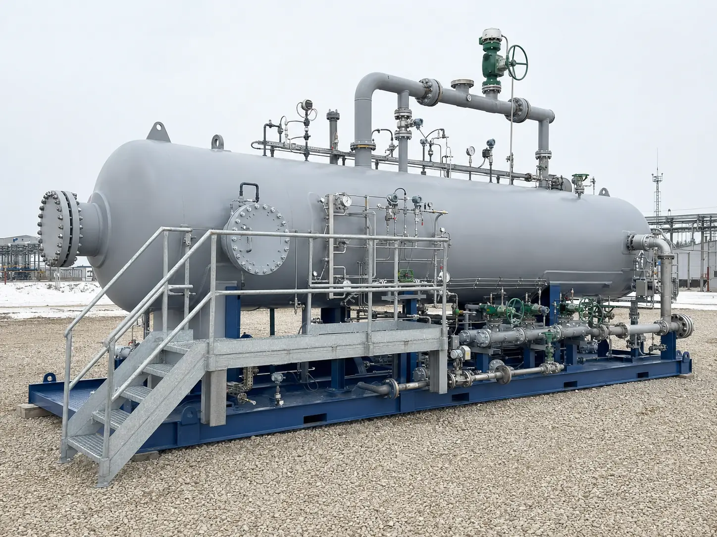
NGSV / TFS / R
Three-Phase Separators
Vessels for simultaneous separation into gas, oil or condensate, and water.
View details EngineeringOil & gas technology
Permanent facility
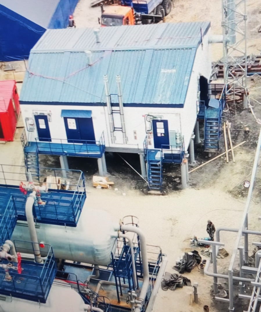
UPSVA permanent facility for early produced-water and gas removal from oil emulsion.
Purpose
Process arrangement
The diagram identifies the principal process duties, equipment connections and product handover points. Final scope, redundancy and battery limits are established from project data.
The simplified diagram identifies the principal process duties and product handover points. Final equipment scope is established from project data.
Engineering basis
Final ratings, materials and supply scope are established from project-specific operating data.
| Capacity | liquid, oil, water and gas rates for design cases |
|---|---|
| Inlet water cut | minimum, normal and maximum |
| Outlet targets | specified residual water in oil and oil/solids in water |
| Design conditions | pressure, temperature, gas-oil ratio and slugging cases |
Process functions
Typical scope
Factory-complete process modules
Interconnecting piping, isolation, control and relief valves
Instrumentation, emergency shutdown and process control
Power distribution, heat tracing, lighting and earthing
Maintenance platforms, shelters and transport provisions as required
Questionnaire
Worked examples and vessel-volume fields are retained. Use them as guidance or provide parameters from an existing design.
Minimum, normal and maximum liquid, oil, water and gas rates
Wellstream composition and physical properties
Inlet pressure and temperature, allowable pressure drop
Required outlet-stream quality and export destinations
Climate, site category, available utilities and transport constraints
Proposal request
Attach the completed questionnaire or provide the principal operating data below. Equipment scope, design ratings and battery limits follow engineering review.
Email the questionnaire, specification and attachmentsFacility composition
The list reflects a typical functional structure. Process stages, redundancy and battery limits are established by engineering calculations.
Vessels for simultaneous separation into gas, oil or condensate, and water.
View details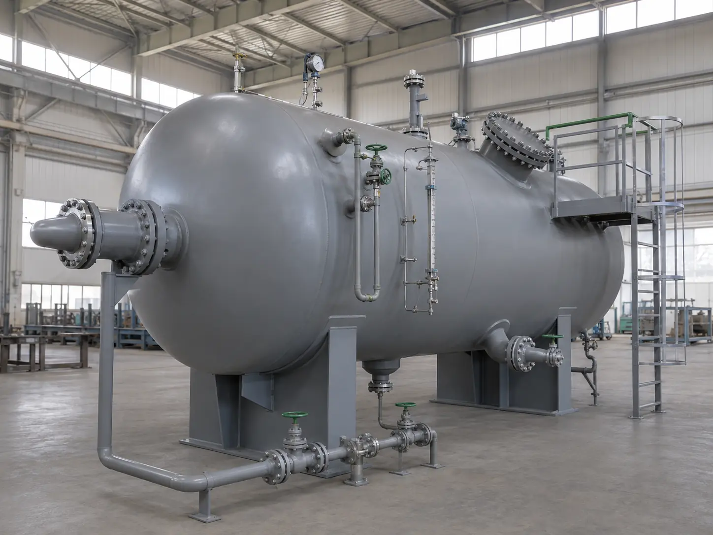
Horizontal vessels for removing oil and suspended solids from produced and process water.
View details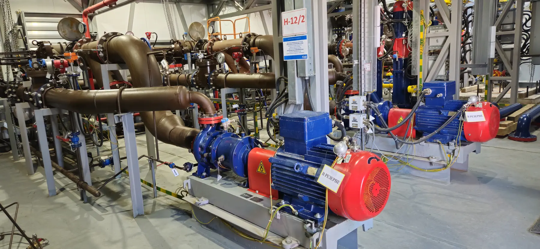
Packaged pumping stations for oil, condensate, water, multiphase streams, wastewater and special fluids.
View details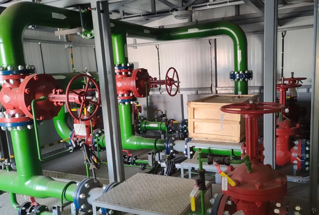
Packaged systems for produced, wastewater, treated-water or injection-water metering.
View detailsRelated scope
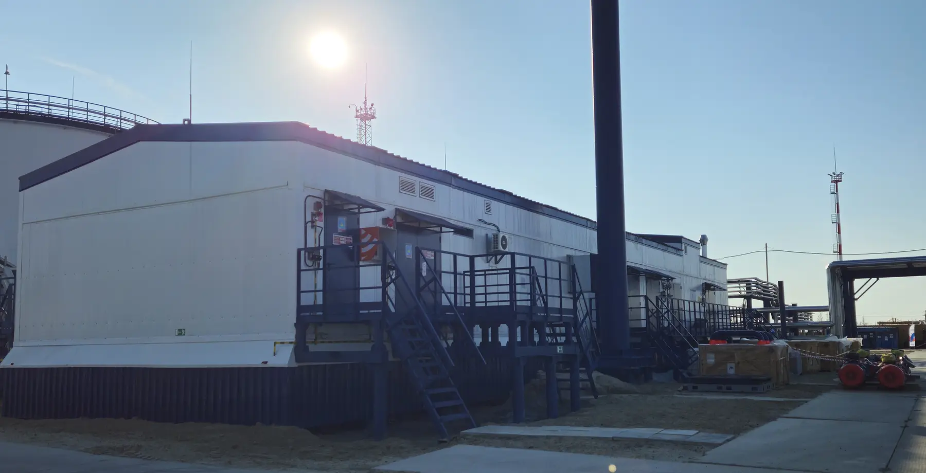
A permanent oil, water and associated-gas treatment facility for long-term field operation.
View details