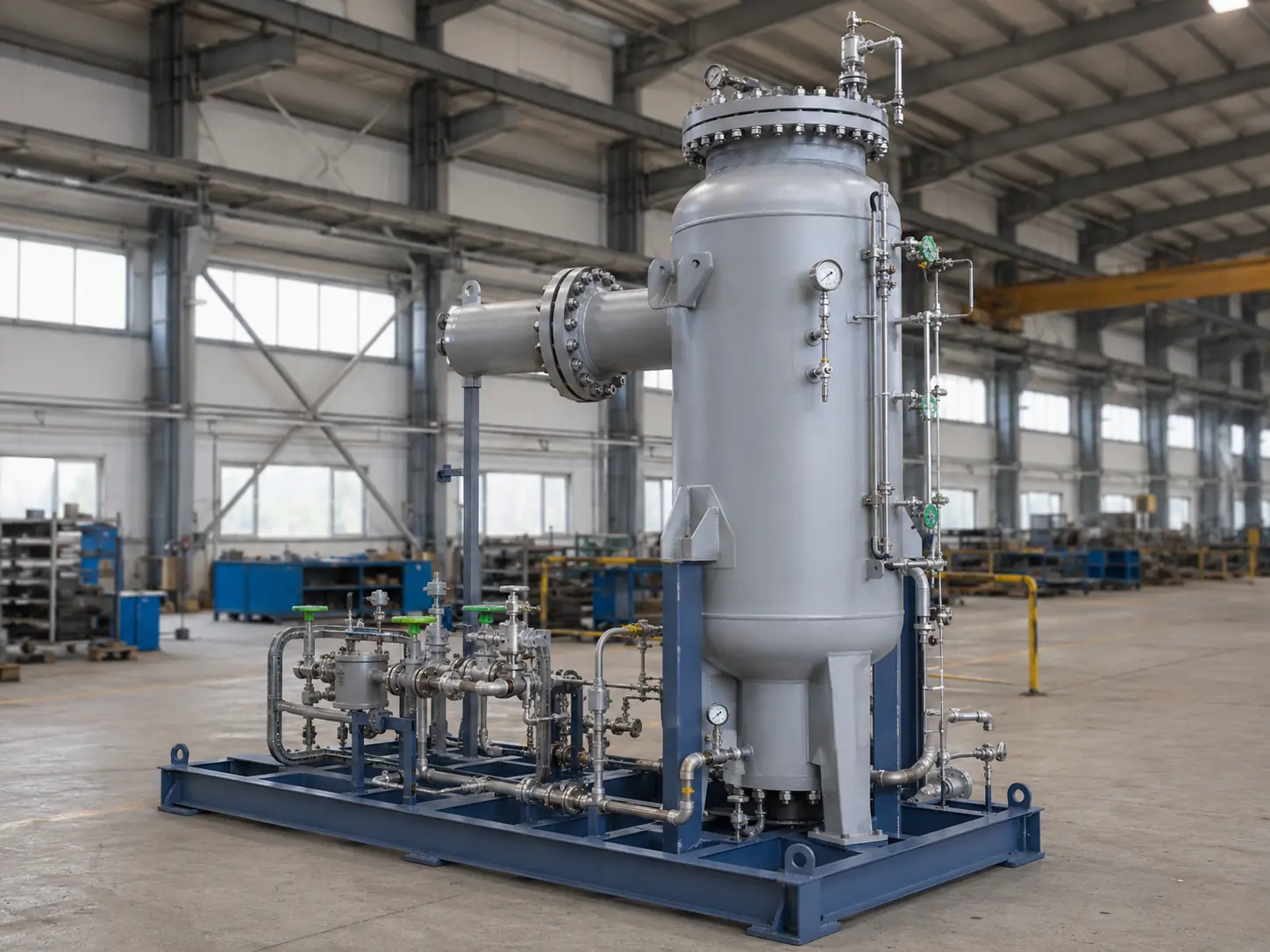
GS / FS / SK
Gas Separators
Gas separators, filter-separators and mesh separators for liquid-droplet and solids removal.
View details EngineeringOil & gas technology
Permanent facility
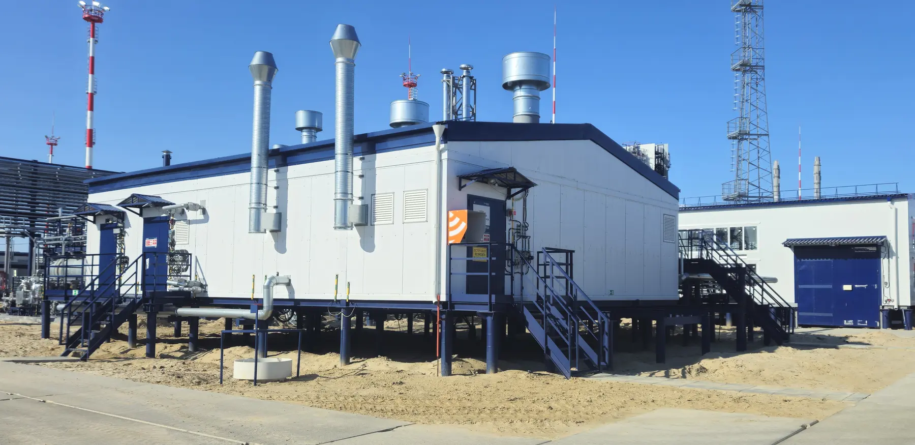
UKPGA permanent facility for gas and condensate separation, sweetening, dehydration and export conditioning.
Purpose
Process arrangement
The diagram identifies the principal process duties, equipment connections and product handover points. Final scope, redundancy and battery limits are established from project data.
The simplified diagram identifies the principal process duties and product handover points. Final equipment scope is established from project data.
Engineering basis
Final ratings, materials and supply scope are established from project-specific operating data.
| Capacity | gas, condensate and water rates for all design cases |
|---|---|
| Treated gas | dew points, pressure, composition and heating value to export specification |
| Process stages | engineered separation, sweetening, dehydration, cooling and compression |
| Execution | project-specific modular or open-plot arrangement |
Process functions
Typical scope
Factory-complete process modules
Interconnecting piping, isolation, control and relief valves
Instrumentation, emergency shutdown and process control
Power distribution, heat tracing, lighting and earthing
Maintenance platforms, shelters and transport provisions as required
Questionnaire
Worked examples and vessel-volume fields are retained. Use them as guidance or provide parameters from an existing design.
Gas composition including H₂S, CO₂, N₂ and heavy hydrocarbons
Flow, pressure and temperature for all operating cases
Dew-point, heating-value and Wobbe-index requirements
Consumer or custody-transfer pressure and specification
Compression, redundancy and acid-gas disposal requirements
Proposal request
Attach the completed questionnaire or provide the principal operating data below. Equipment scope, design ratings and battery limits follow engineering review.
Email the questionnaire, specification and attachmentsFacility composition
The list reflects a typical functional structure. Process stages, redundancy and battery limits are established by engineering calculations.
Gas separators, filter-separators and mesh separators for liquid-droplet and solids removal.
View details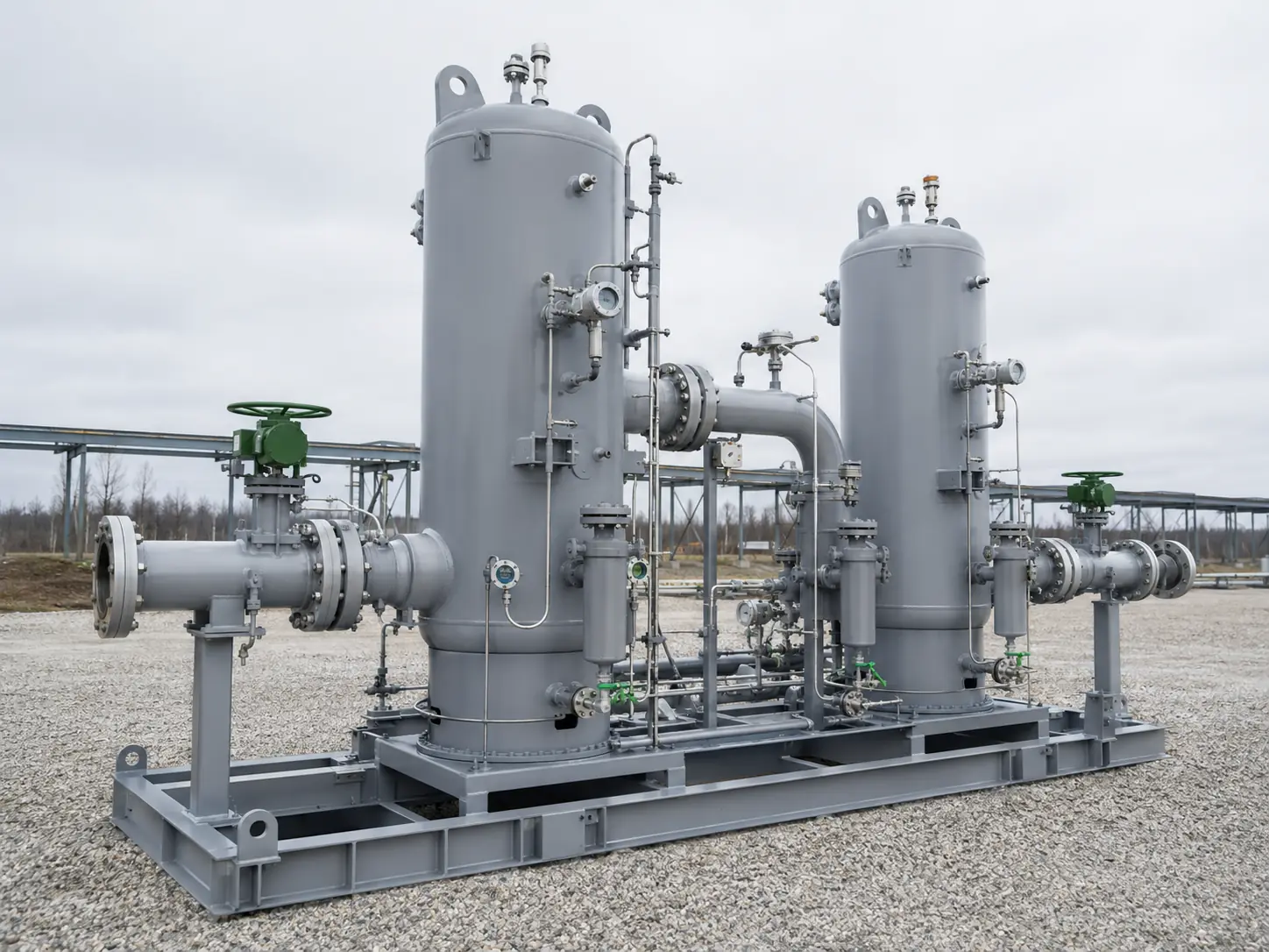
Packaged systems for removing liquid droplets and solids from gas with differential-pressure monitoring.
View details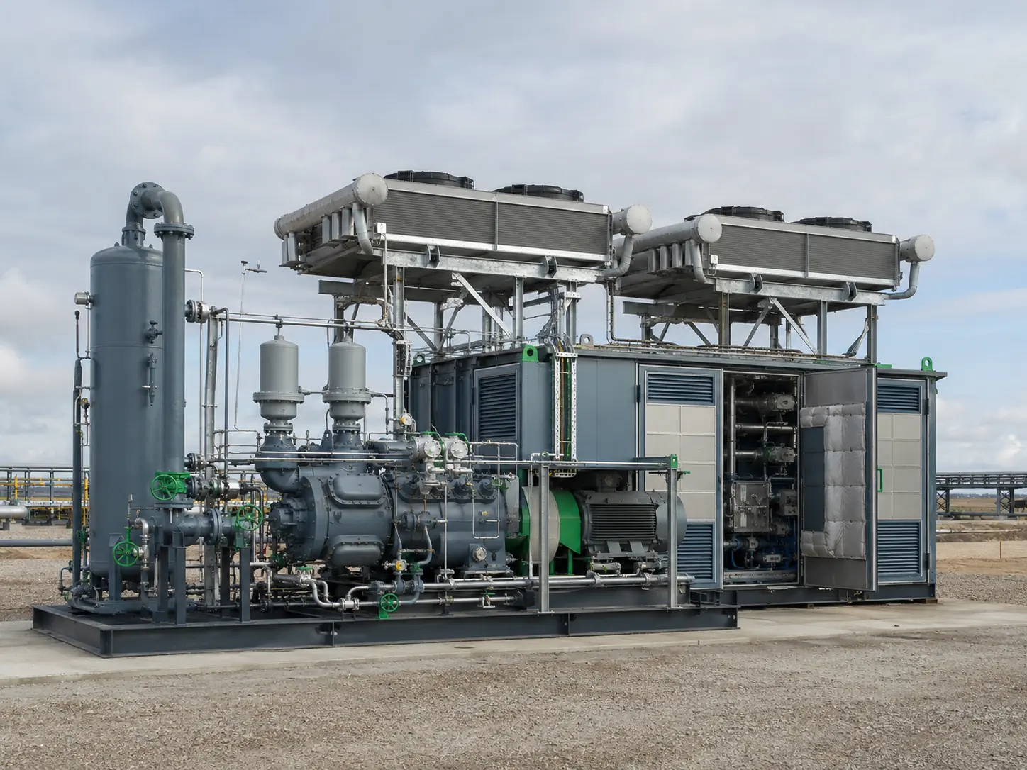
Modular compressor packages for natural, associated and fuel gas.
View details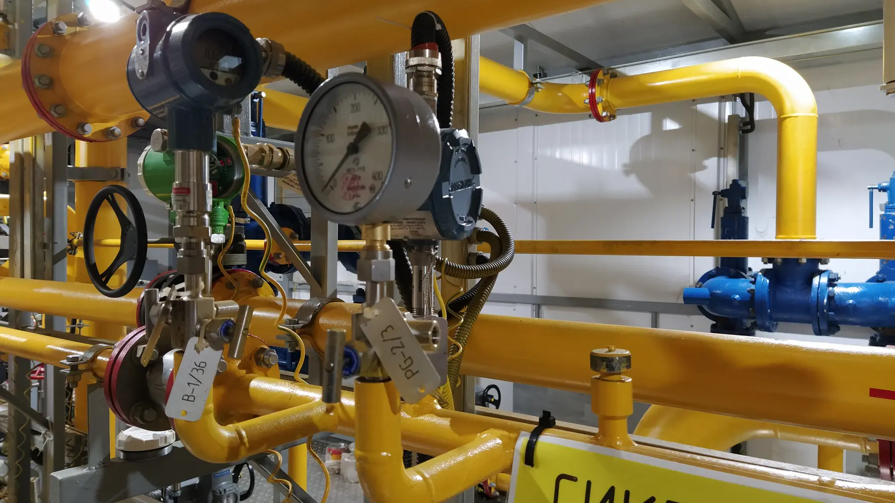
Related scope
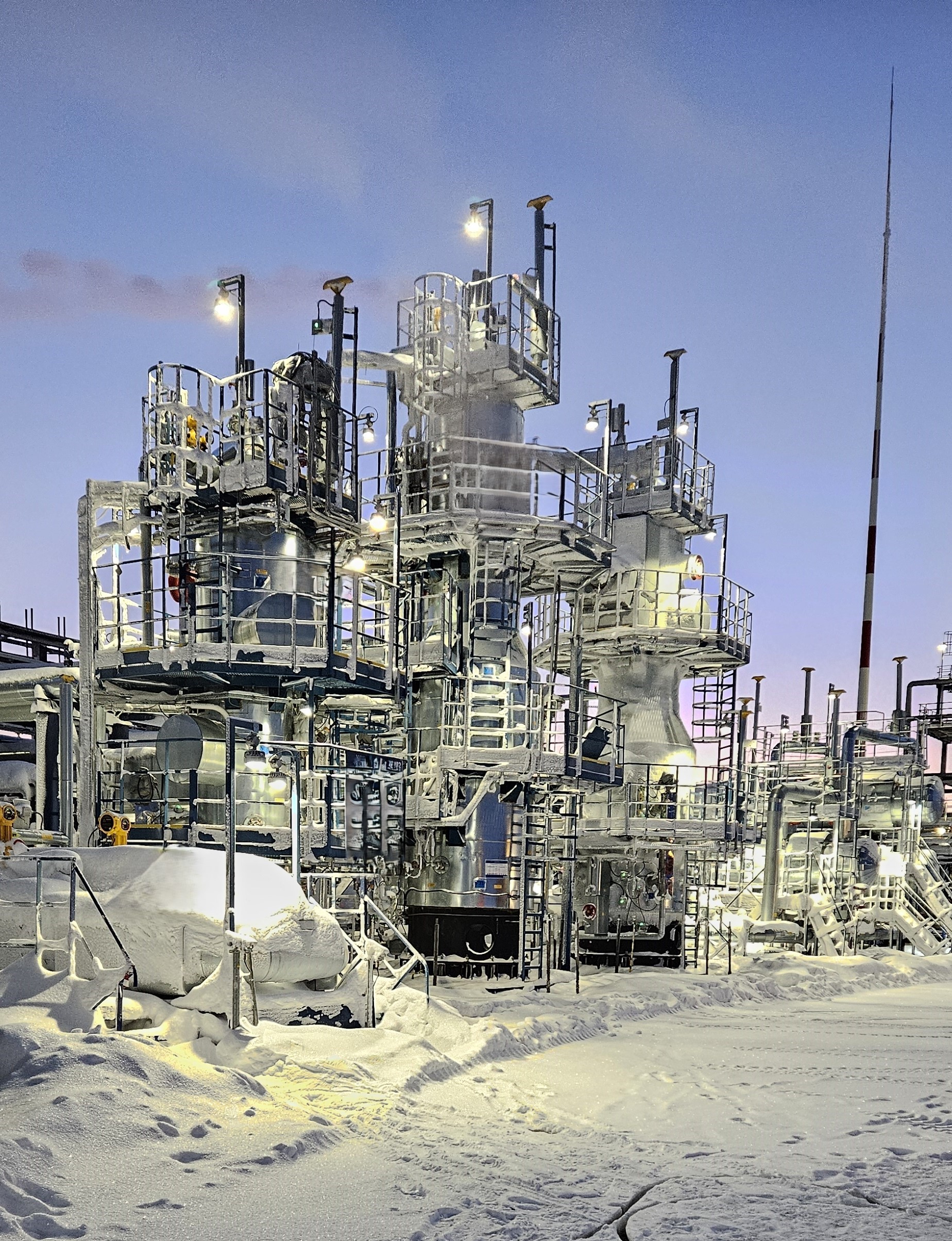
A permanent process system for gas-condensate stabilization and flash-gas handling.
View details